With three murders in a population of about 1500, over the past four years, the annual work related homicide rate for Winnipeg cab drivers has been 50 per 100,000.
This is about 2 1/2 times the rate for both cab drivers and policemen in California; the same as the rate for inmates in U.S. Federal prisons; and 24 times the rate for all male workers in Texas, based on statistics published in the American Journal of Public Health in October, 1987.
Should this homicide rate continue, our taxi community could expect to lose 7 or 8 more of its members in the next 10 years.
Before we dive into this discussion, we suggest you check out taxi-l.org for more useful reports and recommendations.
Appendices:
- A. ECONOMIC ANALYSIS OF TAXICAB SHIELDS
- B. TAXICAB SAFETY REVIEW COMMITTEE
- C. TAXICAB SAFETY SHIELDS TASK FORCE
- D. REGULATION FOR SAFETY SHIELDS
Note: Included in this report are representative samples of certain technical standards upon which Manitoba Regulation 41/90 relies. They are included here only as a convenience and are not displayed in their complete format. In any official application, the original of the documents should be acquired from the sources indicated and subsequently consulted.
Taxi Safety Shields
Background
- In April 1986, taxi driver Gurnam Singh Dhaliwal was the fatal victim of an assault, and steps were then taken to develop and implement a number of safety measures. Among them was the creation of the Fox-Decent Task Force on Taxi Driver Safety.
- As the Fox-Decent group was nearing completion of its work, taxi driver Lawrence Peter Bembin became a fatal victim of an assault in January 1987. In February 1987, as one measure aimed at improving taxi driver safety, that group strongly recommended mandatory safety shields.
- In the following months, considerable debate emerged both for and against mandatory shields, with the local industry itself emerging as a strong opponent. However, a dominant weakness at that time was an apparent inability to find a shield that would not present a significant hazard to a rear seat passenger in event of a collision.
- In the interests of putting some safety measures into place without further delay, the Government in October 1987, declared that safety shields would be made optional, with development work by the industry to be continued.
- On 27 September 1989, taxi driver Paramjit Singh became yet another fatal victim of an assault. The call for action was revived, and on October 10, 1989, Transportation Minister Albert Driedger determined to implement the recommendation of the Fox-Decent Report that safety shields be mandatory for Winnipeg taxicabs, on condition that a design is found that will not jeopardize passenger safety.
- On October 19, 1989, a TAXICAB SAFETY REVIEW COMMITTEE was formed to review safety shields and a variety of other driver safety issues. It was formed of representatives from drivers, owners, government, and various interest groups (See Appendix B). From within that Committee, a pair of Task Forces were formed to deal with:
- a. Taxi Safety Shields (See Appendix C)
- b. All Other Taxi Driver Safety Issues
This report will address the Safety Shields issue. The Taxicab Board cannot design a shield, it cannot build shields, it cannot buy and sell shields, and it cannot give away shields. What the Board can do is define what a safety shield must do, such that taxi industry representatives may negotiate in confidence with suppliers of their choice. This the Board has done, and has a reasonable presumption that the industry will take appropriate initiative soonest.
Executive Summary
Following an extensive review of the local, national, and continental risk; requirements for safety shields, the activities and progress of a selected array of other jurisdictions, contemporary designs, and availability of shields, the Taxi Safety Shields Task Force has concluded that:
- The risk that a taxi driver may be murdered, assaulted, or robbed is dramatically greater now, than it was at the time the Fox-Decent review took place.
- There is a growing awareness throughout North America of the high risk environment in which taxi drivers must work. “Friendly Manitoba” can no longer consider itself immune.
- The requirements for safety shields as perceived by the Fox-Decent review continue to be essentially valid today, and need only be modestly updated.
- The industry that designs and makes shields has acquired a sensitive awareness that minor modifications to police shields is an inappropriate approach, and have successfully designed and built shields specifically for the taxi industry, that will provide reasonable protection for the driver, and reasonable safety for the passenger.
and recommends that:
- the Taxi Safety Review Committee confirm to the Minister of Highways and Transportation that safety shields be made mandatory in taxicabs, as a positive contribution to minimizing opportunities for assaults leading to robbery and/or murder.
- A Regulation, Appendix D, be reviewed, and recommended to the Taxicab Board for implementation immediately, and effective upon first shield approved.
- within 90 days of the effective date, all vehicles capable of accepting an approved shield shall have such a shield installed.
- all vehicles without shields on effective date, because they cannot due to size or other significant impediments as accepted by the Board, be “grandfathered” up to one year, pending individual vehicle replacement.
- all replacing vehicles on or after the effective date be equipped with a safety shield meeting requirements, specifications, and safety inspection.
- the taxi industry be granted a 1 year implementation period, upon expiration of which all remaining vehicles shall be immediately equipped with safety shields meeting the then requirements, specifications, and safety inspection.
Research Into the Risk
Little scientific research into the risks faced by taxi drivers has been done. The National Taxi Driver Safety Council, headquartered in Tampa, FL, reports that in 1988, 34,070 acts of violence were inflicted on taxi drivers in the U.S., from which 253 murders were recorded. No such information is available for Canada. From our three murders of Winnipeg taxi drivers, from a population of about 1500 drivers over the past four years, we can only estimate the annual work related homicide rate against them has been 50 per 100,000.
This is about 2 1/2 times the rate for both cab drivers and policemen in California; the same as the rate for inmates in U.S. Federal prisons; and 24 times the rate for all male workers in Texas, based on homicide statistics published in the American Journal of Public Health in October, 1987.
Should this homicide rate continue, our taxi community could expect to lose 7 or 8 more of its members in the next 10 years.
There is no mechanism for the rapid exchange of information relative to this issue, so the group was faced with the potential of significant delays in gathering needed information to make a fast start.
However, the Task Force learned about the National Taxi Driver Safety Council, and its Executive Director, Jim Szekely, in Tampa, FL. Within a conversation with Mr. Szekely, a recommendation emerged that we contact the 2 most knowledgeable people in North America about Taxi Driver Safety:
Sheila Marshall
Licencing Enforcement Officer
Metropolitan Licencing Commission
Toronto, Ontario
- Capt Don Devine
- Commander
- Boston Hackney Bureau
- Boston, MA, USA
From discussions with these 2 experts, flowed a substantial amount of useful information, itself quickly leading to a wider array of information sources. Their help dramatically reduced the time needed for a proper start.
All documentation made available to the Task Force, principally the Fox-Decent report, revealed only reference to criminal acts inflicted on a sample of the local taxicab industry.
To gain a better appreciation of the risk here, inquiries to the Winnipeg City Police, the RCMP in Winnipeg and Ottawa, MPIC, Winnipeg Taxi Driver Safety Committee, and the Toronto Metropolitan Licencing Commission were directed.
Disappointing results emerged from these inquiries:
- Neither the Winnipeg City Police nor the RCMP have available to them a mechanism to gather data about criminal acts specifically focused on the taxicab industry.
- The Winnipeg Taxi Driver Safety Committee does not have a mechanism to determine and document criminal acts and incidents inflicted on their members. Knowledge of them emerges from informal discussions.
- MPIC does not have information or resources available to them relative to accidents or criminal acts inflicted on the taxicab industry outside Manitoba, resulting in insurance claims.
- Neither Toronto nor Boston have available to them a mechanism to gather information relative to criminal acts inflicted on the taxicab industry outside their own areas.
Capt Don Devine in Boston, and Mr. Angelo Noa in New York, have determined that the single most significant driving force behind these criminal acts is chemical dependency. In most cases, the foreground motive is robbery, and typically for trivial sums of money, for “the next fix”. Taxi drivers are seen as easy “marks”, a mobile cash register just waiting to be opened with remarkable ease.
In a 1988 report, the National Safe Workplace Institute, a U.S. based independent research organization, identified taxi operators as among the most vulnerable workers in society. In their view, shields provide maximum protection and present a simple and relatively inexpensive means to address this “national disgrace”. Taxi fleet owners were urged to immediately install protection. For the Institute, “the issue really boils down to protecting lives”.
The City of New York Police Department strongly advocates the use of safety shields. In their view, “the single most effective deterrent to taxi robberies” is the installation of a shield. Their analysis of all robberies of taxi drivers in New York City indicates that “…more than 70% would have been defeated had a shield been in place…”.
Between 1967 and 1969, there were 10 cab drivers murdered on the job in Boston. As a result, shields were made mandatory. In the 20 years since, not one driver has been the victim of a homicide as a result of an assault from inside the vehicle.
In view of the above, it appears clear that the Winnipeg taxi industry is operating under a false sense of security. True, we pride ourselves that this is “Friendly Manitoba”, that we are far removed from the crime and mayhem of the big cities down south. However, a cursory review of recent local newspaper reports, and discussions with local law enforcement officials clearly reveals that the horrors of drug related crimes are already establishing firmly entrenched footholds. Winnipeg can no longer consider itself immune from these risks.
Other Jurisdictions
1. Toronto
One year ago, the Metropolitan Licencing Commission in Toronto, in response to a rash of murders, assaults, and robberies, commenced a review of safety shields, and of taxi driver safety, much like we did only 4 months ago. On 19 Oct 89, after 13 months of effort, the Commission formally recommended to Toronto City Council that safety shields be made mandatory. It is uncertain how or when that Council will deal with this issue, but are expected to concur.
2. Boston
Twenty years ago, in response to a similar alarming array of murders, assaults and robberies, Boston made safety shields mandatory. They continue to be mandatory to this day, and their presence is credited with a 70% reduction of these types of crimes. Capt. Don Devine, Commander, Hackney Bureau, advises that their dominant fears are directly related to crimes emerging from chemical dependency. Such crimes are most often focused on trivial sums of money.
3. Flint, Michigan
In response to somewhat similar crimes, Flint, Michigan, just 5 months ago, enacted a municipal by-law making safety shields mandatory.
4. Newark, N.J.
In response to somewhat similar crimes, Newark, N.J. enacted a municipal by-law making safety shields mandatory.
5. San Francisco
In response to somewhat similar crimes, San Francisco has recently formed a Taxi Industry Task Force, under the leadership and authority of Deputy Mayor Jerry Lee. They plan a broad overview of both the industry and its economics, along with taxi driver safety.
6. Atlanta
In response to 5 murders in the last 8 months, Atlanta has formed a Task Force, under the authority of the Director of the Bureau of Taxicabs, Mr. Joseph Hall, to review all forms of taxi driver safety, and is targeting his preliminary report for mid-January, 1990.
7. New York
In response to an awesome array of murders and assaults in the Greater New York area, the Taxi & Licencing Commission in the Woodside Borough, under the authority of Deputy Commissioner Angelo Noa, has just formed a Task Force on Taxi Driver Safety, will conduct an in-depth review of safety shields, including their own ballistics tests. Results will be shared with us. Reinstatement of mandatory shields appears likely.
8. Florida
In response to a significant array of criminal acts inflicted upon Florida’s taxicab industry, a proposed Bill has been introduced into their State Legislature to make Safety Shields and Drop Safes mandatory. Debate and decision to come, but appear likely.
9. Other Canadian Jurisdictions
It is not known how many other Canadian jurisdictions, other than Toronto and Winnipeg, are focusing on taxi driver safety to the same degree. To facilitate an exchange of this kind of information, Mr. Doug Cameron, Legal Counsel for the Licencing Division of the Ottawa-Carleton Municipal District has taken the initiative to provoke the formation of a Canadian Association of Taxi Regulators, with a high probability it will emerge in early 1990.
Knowledge of the activities and concerns of the above jurisdictions emerged from out of only 7 weeks review of this high complex issue. It is highly probable that continuing inquiries will reveal a substantially greater number with similar concerns and activities.
The Task Force makes no apologies for clearly primitive research. In the absence of anything better, they believe the critical issue is simply to save lives. No acceptable statistical death rates can be hung on this issue, and every effort must be made to make a taxi driver’s workplace as safe as possible.
Preliminary Shields Requirements
Following is a set of requirements developed from the “ideal” viewpoint of what shields should accomplish. They are currently in the hands of Winnipeg’s Taxi Driver Safety Committee, and a number of manufacturers, and have been favourably received. It is likely that a single shield may not be possible to satisfy all these requirements, but it can come close and provide reasonable protection to the driver, and be reasonably safe for the rear seat passenger.
- From Driver Perspective
- a. Shall deter an armed assault from the rear seat.
- b. Shall provide full height protection, from near floor to ceiling.
- c. Shall provide for bullet resistant protection from the top of the front seat to near floor.
- d. Shall provide for a minimum of bullet deflection from the clear portion of the shield above the front seat.
- e. Shall provide clear, and unobstructed view by the driver through his rear view mirror.
- f. Shall provide for transfer of fare monies through a wide pass-thru on the right side, and this pass-thru device shall not permit entry of a firearm.
- g. Shall provide for a clear center panel, made as wide as possible, that may be lowered to enhance driver/customer communications at discretion of driver.
- h. Esthetics of the clear portion of the shield may be enhanced, as desired, with discreet tasteful frosted trim. Vision shall not be significantly impaired.
- i. Esthetics of the solid portion of the shield may be enhanced, as desired, with a wide variety of painted or upholstered trim.
- j. The total shield may, at discretion of purchaser, be manufactured as an integral part of the front seat, either built right inside, or affixed thereto.
- From Passenger Perspective
- a. The shield shall be suitably padded to minimize injury in event of collision, whereby passenger may be thrown forward into the shield.
- b. The fare pass-thru window shall be so designed of some suitable soft material, such that passengers will not risk injury in a collision where they may be thrown against this device.
- c. The entire shield shall have no solid projections, such as bolt or screw heads, or sharp corners or edges, such as to establish a risk of injury or laceration in event passenger is thrown forward in a collision.
- d. Coincident with shield installation shall be 3-point rear seat belts for 3 rear seat passengers, so designed as to be exceptionally easy to use, and may never be tucked under the cushion.
- e. Esthetics of the total shield may be enhanced, at purchaser’s discretion, to optimize passenger comfort and convenience.
- f. The total shield, or the vehicle, shall be so designed as to provide for a free flow of warm air in winter, and cool air in summer. Passenger shall not be subjected to extremes of climate conditions because of the presence of the shield.
- From Owner Perspective
- a. Shall be so designed as to facilitate transferability to a replacing vehicle.
- b. Shall be designed for simplicity and lo-cost.
- c. Shall be constructed with materials (polycarbons, metal, fabrics, etc) that are fire retardant; resist soiling, vandalism, defacing; and are easily serviced.
- d. Shall not be priced higher than can be contained within a 1.1% rate increase.
- From Other Perspectives
- a. Shall meet all relevant legislation and regulations; and vehicle and safety standards as may be in force under the authority of the Minister of Highways.
- b. Shall meet all relevant legislation and regulations; and occupational and workplace safety standards as may be in force under the authority of the Minister of Environment & Workplace Safety & Health.
Perceived Weaknesses of Shields
Taxi drivers face a number of risk areas, and shields by themselves will not provide the answer nor be the elusive panacea. Shields will provide reasonable protection against an initial assault from the rear seat. However, they are not flawless nor infallible. Some perceived weaknesses:
- “A rear seat assailant need only open the left rear window, and reach a pistol around to threaten the driver through his own door window.”True, this is a known weakness, and a common method of dealing with it is electric door windows. The switch in the rear seat is disabled, so that full control over rear windows rests with the driver only, through his own switch pad controlling all door windows.
- “Shields block the passage of heat in winter, and cooling air in the summer.”To a degree, this is true. Slider type shields restrict air flow the greatest, while vertical retractable shields the least. The heat transfer problem is most commonly solved by the addition of an electric under-seat heater. Improved flow of cool air in summer is being reviewed.Many new cars are coming equipped with rear set heat/cooling vents. With such vehicles, this weakness is no longer a problem.
- “Shields are not truly bullet-proof”True, it is highly probable to a determined assailant, a weapon can be found somewhere that will penetrate a shield. To build a shield that will stop everything would emerge as a formidable barrier, inches thick, with lots of steel. The most significant firearms risk is believed to be small handguns, such as a .38 Special. Most shields will provide good protection from such a weapon, and for the others, will likely deflect the bullet from its intended path. If actual penetration did occur, the bullet would in all likelihood emerge injurious, but non-lethal.In hopes of determining an approximation of the kind of firearms that a taxi driver may one day face, the Winnipeg City Police, the Chief Provincial Firearms Officer, and the RCMP both local and Ottawa were all contacted. All knew how many firearms are registered, but none could tell us the most frequent caliber weapon that might emerge. All that came forth were personal guesstimates ranging from small .22 pistols, to sawed-off shotguns. No reliable information was available.Therefore, for the purposes of standards setting, a presumption has been made that our shields should provide Level 2A ballistics protection according to the National Institute of Justice standard 0108.01, low velocity .357 Magnum/9 mm. This is one step higher than the minimum level of protection provided by this standard.
- “Passengers in the rear seat will be injured upon head contact with the shield in event of collision.”Seat belts have always been mandatory in Manitoba. A rear seat passenger strapped in with a lap belt does indeed risk head contact with the shield. However, the arc of head travel has been determined to impact in the vicinity of the top of the solid lower portion, which is now suitably padded. Rear seat passengers strapped in with 3 point belts have significantly reduced risk of injury for obvious reasons.U.S. legislation requires 3 point belts in all cars commencing with the 1990 model year. Comparable Canadian legislation is a long way off, likely 1993. However, according to the Road Safety Institute in Ottawa, Canadian manufacturers have voluntarily agreed to install 3 point belts commencing with the 1991 model year.The taxi driver is required to remind all passengers that seat belts are mandatory in Manitoba. If they fail to buckle up, they do so at their own risk. As an aid to encourage rear seat passengers to buckle up, it would appear highly appropriate to require the following international pictogram be affixed to the rear face of the shield.
The use of safety belts is compulsory in Manitoba
- “Families of 4; 2 couples, etc., will need 2 cabs, or will alternatively choose to use their own cars.”The presumption that the right hand front seat cannot be used is only partially correct. The driver is encouraged to ordinarily keep that door locked from the inside, and only allow a passenger to sit there if he feels comfortable with that fare.This particular situation, however, is only likely to surface upon a dispatch call where either the pickup or destination point is known, and so recorded. This is ordinarily a lo-risk situation, and a driver may have the discretion to allow that seat to be used. The real risk emerges with “street flags” and the driver would ordinarily exercise caution in any case.
- “Rear seat passenger leg room will be inadequate.”Installation of shields in any car will reduce the available space by approximately 2.5″ to 3″. In any full size car, this will be negligible, and present rear seat space little or no differently than rear seat space currently available to passengers in intermediate or compact cars now being used as taxicabs.Our proposed regulation provides for a minimum of 66cm (26″) from the face of the rear back rest to the safety shield. By comparison, Air Canada has standard spacing of 29″ (74cm) seat-to-seat-to-seat, which coincidentally provides the same 66cm between the face of the back rest to the fold-down tray.
- “Shields will destroy driver/customer communications”The vertically retractable shield offers the least intrusion to driver/customer communications. When down, normal communications will occur without impediment. However, if the driver perceives a risky situation developing, he can choose to raise the shield immediately. During daylight hours, these occasions of risk would ordinarily be apparent to the driver before the customer enters his vehicle.A prudent regulatory requirement will put the shield in the upright position after sunset, and it stays up till sunrise. Driver discretion is still available throughout that period, and depending on his level of comfort with his customer, he may choose to lower the shield after the trip is underway.
Economics of Shields
It has been determined that a 10 year life span may be considered reasonable for an average shield. Most shields encountered in our review were priced well below $1,000 (Can), some as low as $350. Assuming most costly case, $1,000, and a 10 year life, the cost of that shield could be absorbed with a fare increase of .6% to 1.1%. (See attached Appendix A)
The industry periodically tables a submission before the Taxicab Board seeking approval of a fare increase. It would appear quite reasonable that upon next such submission, that portion of such a fare increase applicable to the cost of the shields, could properly be factored into the appropriate formula.
Shield Materials
There are 2 basic materials used in various approaches to shield design – steel and LEXAN.
Steel is most frequently used to provide driver protection from the seat top to near floor. It is normally used in the basic design to also house the mechanism for raising or lowering the clear part of the shield, and to affix the assembly to a rigid floor member.
LEXAN is a GE product, a clear polycarbon type of plastic characterized by extreme toughness, and its ability to at very least deflect a bullet. Some are bullet-proof. MARGARD and MARGON are variations of this product with tough skins designed to minimize marring over long periods.
Basic Design Concepts
For the purposes of this review, 4 basic types of shield design emerged – traditional police, sliding, retractable, and emergency.
Traditional police type shields, while quite appropriate for their needs, are considered totally inappropriate for taxi needs. They have been designed and built to be truly bullet-proof, to contain a criminal or suspect, and have no requirements to be pleasant. Rear seat passengers in such vehicles are normally secured into place by knowledgeable policemen, and no harm will come to either party. They are ominous, intimidating, and are not recommended for taxi purposes.
Sliding shields are those in which a modest portion of the clear section may be slid to one side to facilitate driver-passenger communications. They are ordinarily left in the open position, but a driver, at his discretion, may choose to close and lock it, depending upon perceived risks. These are typically the least costly shields, but do leave in place, an aura of confinement in the perception of a passenger. While technically acceptable for taxi purposes, this type of shield may be recommended.
A retractable shield is one in which a full width clear polycarbon panel that may be lowered into a bullet-resistant container normally affixed to the floor. It has always been available, but at greater cost. It does provide the least significant barrier to driver-passenger communications, and may be raised at will by the driver depending on his assessment of risk. This type of shield is a reasonable compromise, and may be recommended.
An emergency shield is collapsible steel embedded within the seat itself and ordinarily in the retracted position. It may in an emergency situation be instantly raised by the driver to block an imminent assault. In the upright position, a firm barrier to driver-passenger communications is introduced. While costly, this type of shield may be recommended.
Shield Manufacturers
A number of manufacturers were contacted, and some are listed here, but not as a recommendation, only as an indicator. There are certain to be many more manufacturers surface in the foreseeable future in response to normal market and competitive opportunities. This is a healthy situation and one in which the Taxicab Board cannot and will not be a participant.
Over the years, various jurisdictions from time to time, have attempted to resolve the shields issue by mandatory action, similar to our own, that for a variety of reasons failed to actually happen. Consequently, many find it difficult to get interested up front unless we in fact make shields mandatory first. Most wanted firm commitments up front for xxxx shields before they would respond, and preferred to do business directly and only with a single representative of a cab company.
Those that do make shields oriented to taxi cabs, tend to maintain their production facilities by also making and selling shields to police forces. In many cases, the manufacturers clearly were most inclined to do business only in their own local areas, where they and the market were known to each other. Only one manufacturer, Setina, responded positively by designing, building, and bringing one up for demonstration purposes.
The group endeavored to locate a Manitoba manufacturer in a sincere attempt to favour local business. However, manufacturers of safety shields known, or believed to be in this business, are as follows:
- John Setina
- Setina Mfg. Co., Inc
- 2926 Yelm Highway S.E.
- Olympia, WA, 98501
- (206) 491-6197
- Alberto Emistica
- E & B Taxi Meter Service
- 412 East 178 Street
- Bronx, NY, 10437
- (212) 299-2981
- Great Partition Corporation
- 14-15 Inwood Ave
- Bronx, New York 10452
- (212) 538-7272
-
- Al Roggin
- AWR Transportation Inc.
- 3425 Gratiot
- Detroit, MI 48207
- (313) 571-9428
-
- Steve Okopny
- Okan Industries Ltd.
- 6511 Mockingbird Lanes
- Mississauga, ON L5N 5K8
- (416) 681-6991
-
- Oxford Shields
- 16715 – 114 Avenue
- Edmonton, Alta T5M 3P9
- (403) 451-6424
-
- Neville Pather
- Pather Plastics Canada
- 80 Esna Park Drive, Suite #4
- Markham, ON L3R 2R6
- (416) 475-6549
-
- Diego Yepes
- D & M Partitions
- 346 Grand Concourse
- Bronx, NY 10451
- (212) 585-5473
-
- Alexis Ann Homan
- Clearview Partitions
- 3400 14th Ave, Unit 22
- Markham, ON L3R 2L6
- (416) 477-4760
-
- Mario Miotto
- Canadian Armoured Vehicle Builders, Inc.
- 17 Toro Road
- Downsview, ON M3J 2A4
-
-
Local Winnipeg Agents Currently Handling Shields
- Ed deGraaf (also does installs)
- Wilson Industries Ltd
- 4-2166 Notre Dame Ave
- Winnipeg, MB
- 633-6250
-
- Charlie Blackman
- Cen-Can Marketing
- 65 Carriage House Road
- Winnipeg, MB
- 256-9185
-
- Brian Nash
- Carriere Fire & Safety
- 301 Archibald Street
- Winnipeg, MB, R2J 0W6
- 233-7876
Other Considerations
It would be inappropriate for the Government to specifically direct that a certain shield be the only shield acceptable, and consequently likely available from a sole supplier. A more appropriate approach is to promulgate approved specifications, appended to an appropriate regulation, and make them available to all Regulators and manufacturers, with the intent of widespread distribution, and fostering a competitive response to the need.
It is true that safety shields have always been permitted, but few have chosen to install them on the perception of competitive disadvantage. Customers have been thought to avoid using a taxicab equipped with a shield. If all cabs were fitted with these shields, then customer choice is perceived to be no longer a negative factor.
Appendix A
Economic Analysis of Taxicab Shields
The use of a taxicab shield will increase the annual cost of operating a taxicab in three ways:
- The initial cost of acquiring a shield is approximately 1000 dollars. The useful service life of a shield is not known with certainty, but a figure of 10 years will be used in this analysis. Taxicab owners replace their vehicles about every three years on average, but this is not a problem since shields will be required by the Board to be transferable between vehicles. The useful life could well be longer, but the 10 year figure will only help to ensure that any estimate of a required fare increase will truly cover the costs of the shields.A service life of 10 years will result in an additional annual depreciation charge of 100 dollars.
- Assuming that funds will be borrowed to finance the acquisition, and that 15 percent is a realistic rate of interest for borrowing, a shield will result in an additional annual interest expense of 150 dollars.
- Shields will likely require periodic replacement of certain components. For the purpose of this analysis, the Lexan plastic sheet is assumed to require replacement once every 5 years, at a cost of 1/3 of the original cost of the shield. Averaged over time, this represents an additional annual cost of about 70 dollars. It is further assumed that a covering for the shield receptacle will have to be replaced every 2 years at a cost of 20 dollars per replacement, equivalent to an annual cost of 10 dollars.Shield maintenance will therefore result in additional costs of about 80 dollars a year.
The total additional annual cost is estimated at about 330 dollars. The additional meter revenue required to offset this additional cost will depend on the nature of the taxicab operation. If a taxicab is driven only by its owner, the owner requires additional revenue of 330 dollars per year to cover the increased annual cost. If the owner does not drive at all, and shares meter revenues with drivers on a 50/50 basis, the required additional revenue is 660 dollars per year.
Data collected by the Board indicates that 60,000 dollars is a reasonable estimate of the annual meter revenue earned by each taxicab. For a taxicab operation in which only the owner drives, an increase in fares of .55 percent will be sufficient to cover the increased costs of a shield; for an operation in which only hired drivers are used, a fare increase of 1.1 percent will be sufficient.
For an operation in which the driving is done partly by the owner and partly by hired drivers, an increase in fares of between .55 percent and 1.1 percent will be required, depending on how much of the driving is done by hired drivers with whom revenue must be shared. The required fare increase rises as the proportion of hired driver time rises.
Since fares must be increased uniformly for all taxicab operations, an increase of 1.1 percent will be adequate to ensure that all taxicab operations are able to cover the costs of shields.
Appendix B
Taxicab Safety Review Committee
Members
Objective:
To review various taxicab safety devices, tools, techniques, etc., to enhance the safety of a taxi driver’s workplace.
- Don Norquay (Chairman)
- Chairman,
- Taxicab Board
- 200-301 Weston Street
- Winnipeg, MB, R3E 3H4
- 945-8920
-
- Wendy Barker
- Advocacy Chairperson
- Consumers’ Association of Canada
- Room 500, 125 Garry Street
- Winnipeg, MB, R3C 1G5
- 947-3282
-
- George Elliott
- Western Canadian Aviation Museum
- Hanger T2
- 958 Ferry Road
- Winnipeg, MB, R3H 0Y8
- 786-5503
-
- Mel Holley
- Para Legal
- Public Interest Law Centre
- Legal Aid Manitoba
- 402-294 Portage Avenue
- Winnipeg, MB, R3C 0B9
- 947-6501
-
- Inspector Dennis Davill
- Division 17, Traffic
- Winnipeg City Police
- 55 Princess Street
- Winnipeg, MB, R3C 3N6
- 986-6269
-
- Jane Riewe
- Manager
- Support & Development
- Workplace Safety & Health
- 10th Floor, 330 St. Mary Ave
- Winnipeg, MB, R3C 3Z5
- 945-2318
-
- Denys Herbert
- Executive Director
- Manitoba Safety Council
- 202-213 Notre Dame Ave
- Winnipeg, MB, R3B 1N3
- 949-1085
-
- Dan Coyle
- Registrar
- Driver & Vehicle Licencing
- 201-1075 Portage Ave
- Winnipeg, MB, R3G 0S1
- Mr. Don Halbert
- Loss Prevention Manager
- Manitoba Public Insurance Corporation
- 9th Floor, Eaton Place
- 330 Graham Ave
- Winnipeg, MB, R3C 4A5
- 985-7000
-
- Randy Delorme
- Driver
- Duffy’s Taxi
- 10-996 Betournay
- Winnipeg, MB R2J 1E1
- 253-2183
- Peter Kapusta
- Director
- Duffy’s Taxi
- 871 Notre Dame Ave
- Winnipeg, MB, R3E 0M4
- 775-0101 or 772-2451
-
- Alex Jaquet
- Director
- Duffy’s Taxi
- 871 Notre Dame Ave
- Winnipeg, MB, R3E 0M4
- 775-0101 or 772-2451
-
- Tom Springman
- Proprietor
- Spring Taxi
- 880 Logan Ave
- Winnipeg, MB, R3E 1N8
- 774-8294
-
- Gurpal Singh Cheema
- Director
- Unicity Taxi
- 1-458 Mandalay Drive
- Winnipeg, MB, R2P 2C8
- 694 8596
-
- Pritam Brar
- Shareholder
- Unicity Taxi
- 47 Gainsborough Cove
- Winnipeg, MB, R2R 0X1
- 633-6670
-
- Darshan Singh Gill
- Shareholder
- Unicity Taxi
- 18 Hood Avenue
- Winnipeg, MB, R2P 1Y8
- 694-0896
-
- Bhupinder Bains
- Driver
- Unicity Taxi
- 1755 Manitoba Ave
- Winnipeg, MB, R2R 0V7
- 632-0674
-
- Jim Livingstone
- Driver
- Unicity Taxi
- 772 Beverley Street
- Winnipeg, MB, R3E 2A6
- 772-7405
-
- Terry Smythe
- Chief Administrator
- Motor Transport Board
- 200-301 Weston Street
- Winnipeg, MB R3E 3H4
- 945-6713
-
- Charlie Walker
- Secretary
- Taxicab Board
- 214 – 301 Weston Street
- Winnipeg, MB, R3E 3H4
- 945-0289
Appendix C
Taxicab Safety Shields Task Force
Reports To: TAXICAB SAFETY REVIEW COMMITTEE
Objective:
To find or design a taxicab safety shield that on balance will satisfy requirements of driver safety, passenger comfort & safety, and economic viability.
Participants:
Mr. Randy Delorme
- Driver
- Duffy’s Taxi
- 10-996 Betournay Bay
- Winnipeg, MB, R2J 1E1
- 253-2183
- Pritam Brar
- Shareholder
- Unicity Taxi
- 47 Gainsborough Cove
- Winnipeg, MB, R2R 0X1
- 633-6670
-
- Laurie Todd
- Workplace Safety Officer
- Support & Development
- Workplace Safety & Health
- 10th Floor, 330 St. Mary Ave
- Winnipeg, MB, R3C 3Z5
- 945-2318
-
- Adam Hrabinski
- Director, Transport Safety
- Driver & Vehicle Licencing
- 207-1075 Portage Ave
- Winnipeg, MB, R3G 0S1
- 945-8925
-
- Terry Smythe
- Chief Administrator
- Motor Transport Board
- 200-301 Weston Street
- Winnipeg, MB R3E 3H4
- 945-6713
Appendix D
Regulation for Safety Shields
-
Final Approved Version
-
15 Feb 90
- THE TAXICAB ACT
- (C.C.S.M. c. T10)
- Taxicab Safety Shield Regulation
- Regulation 41/90*
- Registered February 14, 1990
Definitions
1. In this regulation,
- “board” means the Taxicab Board
- “CMVSS” means a Canadian Motor Vehicle Safety Standard established by regulation under the Motor Vehicle Safety Act (Canada);
- “handicab van” means a taxicab that is equipped as provided in section 48.1 of the Taxicab Regulation and is licenced by the board for the transportation of handicapped persons in wheelchairs;
- “limousine” means a taxicab, other than a passenger van, with a seating capacity of 7 or more persons, including the driver;
- “operator” means a person who operates a taxicab or a person on whose behalf a taxicab is operated;
- “passenger van” means a taxicab of a van configuration with a seating capacity of 11 or more persons, including the driver;
- “shield” means a partition designed for installation in a taxicab to increase the safety of the driver from violent crime;
- “substitute taxicab” means a vehicle permitted by the board to be operated under a taxicab licence on a temporary basis in substitution for a vehicle which is being repaired.
Application
2 (1) This regulation does not apply to a
- (a) handicab van;
- (b) limousine;
- (c) passenger van; or
- (d) substitute taxicab.
2 (2) This regulation applies to operators in respect of taxicabs 90 days after the board first approves the design of a shield under subsection 4(1).
Safety shield required
3 Subject to subsection 5(3), an operator shall
- (a) at all times that the taxicab is operated,ensure
- (i) that the taxicab is equipped with a shield in such a manner that the taxicab and shield comply with
- (A) The specifications set out in the Schedule; or
- (B) the specifications set out in the Schedule as varied by an order under subsection 5(2); and
- (ii) that the shield is of a design approved by the board in accordance with section 4; and
- (i) that the taxicab is equipped with a shield in such a manner that the taxicab and shield comply with
- (b) prior to the operation of the taxicab after its being equipped with the shield, have the installation of the shield inspected and approved by the Division of Driver and Vehicle Licencing of the Department of Highways and Transportation.
Approval of design4(1) The board may approve designs of shields and
- (a) in determining whether or not to approve a shield of a particular design may consider
- (i) its probable cost, and
- (ii) its appearance; and
- (b) shall not approve a shield of a particular design unless
- (i) it complies
- (A) with the specifications set out in the Schedule, or
- (B) with the specifications set out in the Schedule as varied by an order under subsection 5(2), and
- (ii) a qualified independent testing laboratory has certified that
- (A) the shield complies with clause 4(a), section 5 and clause 7(a) of the Schedule, and
- (B) the results of all tests of shields of the same or a substantially similar design performed by the laboratory are disclosed to the board.
- (i) it complies
4(2) The board shall give notice in writing of its first approval of the design of a shield to all holders of taxicab licences by ordinary mail as soon as practicable after that approval, but no failure to give notice shall affect any obligation imposed by this regulation.
Exceptions where taxicab in service
5(1) This section applies to operators in respect of taxicabs that are in service on the date of the board’s first approval of the design of a shield under subsection 4(1).
5(2) Where the board is satisfied
- (a) that the only respects in which the taxicab and shield do not comply or cannot feasibly be made to comply with the specifications set out in the Schedule are
- (i) the limitation of the rearward adjustment of the front seat as required in section 9 of the Schedule,
- (ii) the leg room or foot room required by section 10 of the Schedule, or
- (iii) both (i) and (ii): and
- (b) that it would not be feasible to install a shield in the taxicab without a variation of one or more requirements described in clause (a);
the board may make an order varying the requirements of the specification described in clause (a), if, after considering the number of taxicabs in respect of which an order may be made, the board is of the opinion that to do so would be in the public interest.5(3) where the board is satisfied that a taxicab cannot feasibly be equipped so as to comply with subclause 3(a)(i), the board may make a determination in respect of that taxicab to that effect and thereafter section 3 does not, for a period of two years after the date of the first approval of the design of a shield under subsection 4(1), apply to the operator in respect of the taxicab.
Exception where taxicab equipped with shield on February 10, 1990
6. Notwithstanding sections 3, 4 and 5 of this regulation, where
- (a) on February 10, 1990 a taxicab was equipped with a shield; and
- (b) the taxicab was in service on February 10, 1990 and on the date of the board’s first approval of the design of a shield under subsection 4(1);the operator of the taxicab may operate it equipped with the shield until
- (c) the taxicab ceases to be equipped with the shield; or
- (d) the taxicab ceases to be in continuous service;
whichever is the earlier.
Shield to be kept closed
7(1) Subject to subsection (2), a driver of a taxicab equipped with a shield in accordance with section 3 or section 6 shall, at all times between sunset and sunrise when a passenger first enters and is in the passenger section of the taxicab, ensure that the sliding or retractable portion of the shield is closed.
7(2) A driver may open the sliding or retractable portion of the shield when a passenger is in the passenger section of the taxicab if the driver believes in good faith that to do so does not pose a risk of harm to him or her.
M.R. 44/90
Driver’s right to refuse front seating or assistance to passengers
8 A driver of a taxicab equipped with a shield in accordance with section 3 or section 6 may refuse
- (a) to permit any passenger to enter the driver section of the taxicab unless the passenger due to physical disability cannot enter or be seated in the passenger section; or
- (b) to provide assistance to any passenger if the driver of the taxicab believes in good faith that to do so would pose a risk of harm to him or her.
February 13, 1990
- THE TAXICAB BOARD:
- D.S. Norquay
- Chairman
- C. S. Walker
- Secretary
* All persons making use of this consolidation are reminded that it has no legislative sanction. Amendments have been inserted into the base regulation for convenience of reference only. The original regulation should be consulted for purposes of interpreting and applying the law. Only amending regulations which have come into force are consolidated. This Regulation consolidates the following amendments: 44/90.
1 Subject to section 14, the shield shall
- (a) partition the taxicab into a passenger section and a driver section; and .
- (b) form a complete barrier between the passenger section and the driver section, which effectively prevents physical contact between a person in the passenger section and the driver.
2 The shield shall be anchored to the structure of the taxicab in a manner which meets the most stringent requirements of CMVSS 207 for anchorage of seats and CMVSS 210 for seat belt assembly anchorages.
3 The shield shalt not allow passage of any object capable of physical harm through or around it, from one section of the taxicab to the other, subject to the standards in clauses 4(a), 5(b) and 5(c).
4 The portion of the shield between the floor and the top of the front seat of the taxicab shall be
- (a) primarily constructed of steel plate or other material of a thickness which allows that portion of the shield to meet or exceed the ballistic resistance requirements specified by National Institute of Justice Standard-0108.01 for ballistic resistant protective materials to be used as protection against a Type II-A ballistic threat, or the requirements of another comparable standard acceptable to the board; and
- (b) covered with a material similar to the seat covering of the taxicab, over a layer of energy absorbing material.
5 The portion of the shield between the top of the front seat and the ceiling of the taxicab shall be primarily constructed of a transparent material which meets or exceeds
- (a) American National Standards Institute Standard Z26.1-1983 for safety glazing materials as it relates to interior partitions for taxicabs;
- (b) the ballistic resistance requirements specified by National Institute of Justice Standard – 0108.01 for ballistic resistant protective material to be used as protection against a Type II-A ballistic threat, or the requirements of another comparable standard acceptable to the board; and
- (c) the forced entry requirements of H. P. White Laboratories standard HPW-TP-0100.00 for material to be used as a Level I protective barrier, or the requirements of another comparable standard acceptable to the board.
6 The portion of the shield between the top of the front seat and the ceiling of the taxicab shall not obscure or obstruct the clear view of the roadway to the rear of the taxicab or of any vehicle approaching from the rear, afforded by the inside rear view mirror installed in accordance with subsection 42(1) of the Highway Traffic Act and CMVSS 111.
7 The taxicab shall comply with every prevailing CMVSS, and particularly
- (a) the taxicab shall comply with CMVSS 201 for occupant protection as it relates to seat backs, through the use of energy absorbing material on the shield over the head impact area of a 95th percentile adult who is restrained in the rear seat by a pelvic seat belt and whatever other means are necessary to meet the standard;
- (b) the shield shall not interfere with the performance of the headrests in accordance with CMVSS 202; and
- (c) the shield shall not interfere with the performance of the seat belts in accordance with CMVSS 208 and CMVSS 209.
8 The shield shall not have any edge or projection that may cause injury.
9 The shield shall allow full forward and rearward adjustment of the front seat to within 5 cm or less of its most rearward adjustment as provided by the manufacturer.
10 The shield shall allow for a minimum of
- (a) 68 cm of leg room in both side seating positions of the rear seat, measured from the center of the seating positions where the seat back meets the seat cushion, across the seat cushion and a straight line extension thereof perpendicular to the shield; and
- (b) 48 cm of foot room in both side seating positions of the rear seat measured from the front of the base of the rear seat cushion across the floor perpendicular to the shield, by means of an extension of the shield under the front seat at least 36 cm wide and 14 cm high.
11 A means shall be provided for
- (a) adequate ventilation and heating of the passenger section of the taxicab; and
- (b) audible communication between the passenger and the driver.
12 The shield shall have an opening through which payment of fares and provision of receipts can be made.
13 The shield shall be capable of removal and reinstallation in a replacement vehicle.
14 At least 40x of the area of the transparent section of the shield shall slide or retract open by a mechanism under the control of the driver,
- (a) which shall not be capable of accidental activation; and
- (b) which shall be readily accessible to the driver when he or she is seated in the driver’s seat.
15 The shield shall bear the name of the manufacturer and the number of the design approval given with respect to the shield by the board.
The Queen’s Printer for the Province of Manitoba
Consolidation of The
MOTOR VEHICLE SAFETY ACT
MOTOR VEHICLE SAFETY REGULA IONS
AUTHORIZATION OF MINISTER OF TRANSPORT TO DETERMINE
FEES REGULATIONS
Revised as of 1 April 1989
Prepared by
Departmental Secretariat, Policy and Coordination Group
in collaboration with the
Road Safety and Motor Vehicle Regulation Directorate
Transport Canada
Distributed by
Standards and Regulation Division
Road Safety and Motor Vehicle Regulations Directorate
*The Consolidation of the
Motor Vehicle Safety Act
Motor Vehicle Safety Regulations
are available in Canada through
Authorized Bookstore Agents and other bookstores or by mail from
- Canadian Government Publishing Centre
- Supply and Services Canada
- Ottawa, Canada KlA OS9
- Catalogue No. YX76-M10-1989E
- Canada: $63.85
Price subject to change without notice
IMPORTANT NOTE FOR USERS
Users of this consolidation are cautioned that it has been prepared for use as a ready reference and has no legal force or effect. For all purposes of interpreting and applying these regulations, users should consult the Revised Statutes o Canada 985 and the consolidated Re lations o Canada, 1978 and any pertinent amending statutory instruments, as published in the Canada Gazette. Part II.
EXPLANATION
This booklet is divided into three parts; Index Motor Vehicle Safety Act, and Motor Vehicle Safety Regulations.
The index is inserted for convenience of locating a particular section or safety standard within the Motor Vehicle Safety Regulations. The index is not part of the official Regulations.
The pages of the Regulations are not numbered in the conventional manner but by the applicable number of the section or the number of the safety standard (CMVSS). These page numbers are located on the upper corner of the page. Example: MVSR 108-8 is page 8 of CMVSS 108 “Lighting Equipment”. These numbers (ie. 108) for the most part equate to the numbering system used by the United States National Highway Traffic Safety Administration for their safety standards.
This Consolidation of the Regulations comprises the CONSOLIDATED REGULATIONS OF CANADA, 1978 (CRC) Chapter 1038 and amendments published in Part II of the Canada Gazette up to April 1, 1989. The amending Statutory Instruments (SOR) are listed at the end of each section or safety standard with a description of what was amended and its effective date.
To obtain amendments to the Regulations and the Act subsequent to April 1, 1989, contact the:
Canadian Government Publishing Centre,
- Supply and Services Canada
- Ottawa, Canada
- K1A OS9
- Tel: 819-997-2560
- Telex: 0534296
- FAX: 819-994-1498
DOCUMENTS REFERRED TO IN THE REGULATIONS
American Association of Textile Chemists and Colorists documents may be ordered at the address: Post Office Box 886, Durham, NC., .
American National Standards Institute documents may be ordered at the address: 1430 Broadway, New York, NY 10018
Motor Vehicle Manufacturers’ Association address is 25 Adelaide Street East, Toronto, Ontario M5C lY7, Fax (416) 367-3221 or CNCP Dialcom 2l:MVMOO1
Motor Vehicle Safety Test Methods may be obtained by contacting: Regulation Clerk, Road Safety and Motor Vehicle Regulation Directorate, Transport Canada, 344 Slater Street, Ottawa, Ontario. RlA ON5 Tel: (613) 998-1960
Society of Automotive Engineers, Inc. (SAE) documents may be ordered by contacting: Customer Service, SAE, 4o0 Commonwealth Drive, Warrendale, PA. 15096 Tel:(412) 776-4970
INQUIRIES
Inquiries concerning the Motor Vehicle Safety Act, Motor Vehicle Safety Regulations and the incorporated references should be directed to the Road Safety and Motor Vehicle Regulation Directorate, Transport Canada, 344 Slater Street, Ottawa, Ontario KlA 0N5.
Principal contacts within the Directorate:
- Compliance Engineering and vehicle Testing (613) 993-7875
- Component Testing, Importation and Audit Inspection (613) 998-2174
- Energy and Emissions Engineering (613) 993-4981
- Public Complaints, Recalls and Investigations (613) 998-3981
- Standards and Regulations (613) 998-1957
OTHER RELATED ACTS AND REGULATIONS
The following documents are available from
Canadian Government Publishing Centre,
- Supply and Services Canada
- Ottawa, Canada
- K1A 0S9
- Tel: 819-997-2560
- Telex: 0534296
- FAX: 819-994-1498
Authorization of the Minister of Transport to Determine Fees Regulations, SOR/85-860 – $2.50
Motor Vehicle Test Centre Fees Order, SOR/86-191 — $3.00
Motor Vehicle Tire Safety Act, R.S.C. 1985, Chapter M-11 – $4.00
Motor Vehicle Tire Safety Regulations, C.R.C.,c.1039 and amendments – $20.50
Transport Canada departmental consolidations may be obtained on microfiche from the Canadian Government Publishing Centre as above or from M. J. Monaghan, Departmental Registrar, Transport Canada, Tower C, Place de Ville, Ottawa, Ontario. K1A 0N5. Tel: (613) 991-6593 of:
- (a) The Motor Vehicle Safety Act, Regulations, Test Methods and Test Centre FeesCatalogue Number- Basic Set YX75-1-26-1-F.M — $14.80;- Amendment Service SUP1-26EM- $15.75
- (b) The Motor Vehicle Tire Safety Act, Regulations and Test MethodsCatalogue Number- Basic Set YX79-1974-6-96-1-EM- $3.50- Standing Order Service for amendments YX79-96EM
Subscribers will receive amendments as they appear with a covering invoice.
MVSR 207 – 1
Anchorage of Seats
207. (1) Each vehicle shall have an occupant seat for the drives and such occupant scat and all other occupant seats except n side-facing seat or a bus passenger seat shall, when subjected to Motor Vehicle Safety Test Methods, Section 207, Anchorage of Seats, approved December 7, 1973, withstand, when installed in the vehicle
- (a) in any position to which it can be adjusted,
- (i) the application of a force equal to 20 times the weight of the seat applied separately in
- (A) a forward, and –
- (B) a rearward
longitudinal direction through the centre of gravity of the seat, and
simultaneously, in the case of a seat having one or more seat belt assemblies attached directly to it,
- (ii) the application of a force equal to the total load imposed on the seat by simultaneous application in the directions referred to in clauses (i)(A) and (B) of the respective loads required by section 210 of this Schedule for.the seat belt assemblies so attached; and
- (i) the application of a force equal to 20 times the weight of the seat applied separately in
- (b) in its rearmost position, application of a force that
- (i) produces a moment of 3,300 pound-inches about the seating reference point tor each designated seating position for which the occupant seat is designed, and
- (ii) is applied to the upper seat back or the upper cross-member of the seat back
- (A) in a rearward longitudinal direction for forward- facing seats, and .
- B) in a forward longitudinal direction for rearward- facing seats.
.
(2) Except for vertical movement of non-locking suspension type occupant seats in trucks or buses, no occupant seat shall change its position adjustment during any application of force referred to in paragraphs (1)(a) and (b).
(3) Except in the case of a passenger seat in a bus and a seat having a back that is only adjustable for the comfort of the occupant, a hinged or folding occupant seat or occupant seat back shall be equipped with
- (a) a self-locking device for restraining the hinged or folding seat or seat back, and
- (b) a control for.releasing the self-locking device.
(4) Where a designated seating position is immediately behind a seat equipped with the self-locking device referred to in subsection. (3), the control for releasing the device shall be readily accessible to
- (a) the occupant of the seat equipped with the device; and
- (b) the occupant of the designated seating position immediately behind such seat if access to the control is required in order to allow him to exit from the vehicle.
(5) The self-locking device referred to in subsection (3) shall not release or fail when
- (a) in the case of a forward-facing seat, a forward longitudinal force equal to 20 times the weight of the hinged or folding portion of the seat is applied through the centre of gravity of that portion of the seat;
- (b) in the case of a rearward-facing seat, a rearward longitudinal force equal to eight times the weight of the hinged or folding portion of the seat is applied through the centre of gravity of that portion of.the seat; and
- (c) subjected to an acceleration of 20g in the longitudinal direction opposite to that in which the seat folds.
(6) Seats not intended for occupancy while the vehicle is in motion shall bear a conspicuous label that so states in English and in French.
MVSR 210 – 1
Seat Belt Assembly Anchorages
210. (1) In this section,
” anchorage ” means the provision for transferring seat belt assembly loads to the vehicle structure; ‘
” convertible ” means a passenger car having a top or roof that can be installed, erected, folded, retracted, dismantled or removed at the convenience of the user, but excludes an open-body type vehicle;
” fore ” means the direction in which the occupant of a seat faces when seated normally in such seat.
(2) Subject to subsection (3), anchorages for a Type 1 or Type 2 seat belt assembly shall be installed in a vehicle for each designated seating position except in the case of a passenger seat in a bus.
(3) Anchorages for a Type 2 seat belt assembly shall be installed in a passenger car other than a convertible for each forward-facing outboard designated seating position, and in vehicles other than passenger cars for each designated seating position for which a Type 2 seat belt assembly is required by section 208 of this Schedule.
(4) Except in the case of side-facing seats, the anchorage for a Type 1 seat belt assembly or the pelvic portion of a Type 2 seat belt assembly shall withstand a 5,000 pound force when tested in accordance with subsection (13).
(5) The anchorage for a Type 2 seat belt assembly shall withstand simultaneous 3,000-pound forces when tested in accordance with subsection (14).
(6) Permanent deformation or rupture of an anchorage or its surrounding structure shall not be considered a failure to comply with subsections (4) and (5) if the required force is maintained for 10 seconds.
(7) Except in the case of common anchorages for forward- facing and rearward-facing seats, floor-mounted anchorages for adjacent designated seating positions shall be tested by simultaneously loading the seat belt assemblies attached to such anchorages.
(8) In the case of a seat belt assembly in which the seat belt does not bear upon the seat frame, a line from
- (a) the seating reference point in the case of a non- adjusting seat, or
- (b) a point 2.50 inches to the fore of and 0.375 inch above the seating reference point in the case of an adjustable seat in its rearmost position,
to the nearest contact point of the belt with the anchorage shall extend to the fore from that contact point at an angle with the horizontal of not less than 20 degrees and not more than 75 degrees.
(9) In the case of a seat belt assembly in which the belt bears upon the seat frame, an anchorage not on the seat structure shall be aft of the rearmost contact point of the belt on the seat frame with the seat in its rearmost position, and the line from the seating reference point to the nearest contact point of the belt with the seat frame shall extend to the fore from that contact point at an angle with the horizontal of not less than 20 degrees and not more than 75 degrees.
(10) In the case of a seat belt assembly in which the seat belt anchorage is on the seat structure, the line from the seating reference point to the nearest contact point of the belt with the anchorage shall extend to the fore from that contact point at angle with the horizontal of not less than 20 degrees and not more than 75 degrees.
(11) Anchorages for an individual seat belt assembly shall be located at least 6.50 inches apart laterally as measured between the vertical centrelines of the bolt holes.
(12) The seat belt anchorages for the upper end of an upper torso restraint shall be located within the acceptable range shown in Figure 4 Upper Torso Restraint contained in SAE Standard J787b (September 1966), with reference to a two dimensional manikin described in SAE Standard J826, (November 1962), the H-point of which is at the seating reference point and the torso line of which is at the same angle from the vertical as the seat back with the seat in its full rearward and downward position and the seat back in the manufacturer’s nominal design upright position.
(13) A force of 5,000 pounds shall be applied and maintained for 10 seconds in the direction in which the seat faces and with the seat in its rearmost position to a pelvic body block restrained by a Type 1 or the pelvic portion of a Type 2 seat belt assembly, as applicable, in a plane parallel to the longitudinal centreline of the vehicle at an initial force application angle of not less than 5 degrees and not more than 15 degrees above the horizontal and at an onset rate of not more than 50,000 pounds per second so as to attain the 5,000-pound force in not more than 30 seconds.
(14) Forces of 3,000 pounds shall be applied simultaneously and maintained for 10 seconds in the direction in which the seat faces and with the seat in its rearmost position to pelvic and upper torso body blocks restrained by a Type 2 seat belt assembly in a plane parallel to the longitudinal centreline of the vehicle at an initial force application angle of not less than 5 degrees and not more than 15 degrees above the horizontal and at an onset rate of not more than 30,000 pounds per second so as to attain the 3,000-pound force in not more than 30 seconds.
(15) The pelvic body block referred to in subsections (13) and (14) shall conform to the dimensions set out in Figure 7 Typical Body Block For Lap Belt Anchorage contained in SAE Standard J787b, (September 1966).
(16) The upper torso body block referred to in subsection (14) shall conform to the dimensions set out in Figure 6 Typical Body Block For Combination Shoulder And Lap Belt Anchorage contained in SAE Standard J787b, (September 1966).
U.S. Department of JusticeNational Institute of Justice
Technology Assessment Program
Ballistic Resistant
-
Protective Materials
-
NIJ Standard 0108.01
September 1985
FOREWORD
This standard is a technical document that specifies performance and other requirements equipment should meet to satisfy the needs of criminal justice agencies for high quality service. Purchasers can use the test methods described in this standard to determine whether a particular piece of equipment meets the essential requirements, or they may have the tests conducted on their behalf by a qualified testing laboratory. Procurement officials may also refer to this standard in their purchasing documents and require that equipment offered for purchase meet the requirements. Compliance with the requirements of the standard may be attested to by an independent laboratory or guaranteed by the vendor.
Because this NIJ standard is designed as a procurement aid, it is necessarily highly technical. For those who seek general guidance concerning the selection and application of law enforcement equipment, user guides have also been published. The guides explain in nontechnical language how to select equipment capable of the performance required by an agency.
NIJ standards are subjected to continuing review. Technical comments and recommended revisions are welcome. Please send suggestions to the Program Manager for Standards, National Institute of Justice, U.S. Department of Justice, Washington, DC 20531.
Before citing this or any other NIJ standard in a contract document, users should verify that the most recent edition of the standard is used. Write to: Chief, Law Enforcement Standards Laboratory, National Bureau of Standards, Gaithersburg, MD 20899.
Lester D. Shubin
- Program Manager for Standards
- National Institute of Justice
CONTENTS
Foreword
- Purpose
- Scope and Classification
- Definitions
- Requirements
- 4.1 Acceptance Criteria
- 4.2 Workmanship
- 4.3 Labeling
- 4.4 Ballistic Resistance
- Test Methods
- 5.1 Sampling
- 5.2 Test Equipment
- 5.3 Ballistic Resistance Test
- Appendix A-References
NIJ Standard-0108.01
- NIJ STANDARD
- FOR
- BALLISTIC RESISTANT
- PROTECTIVE MATERIALS
1. PURPOSE
The purpose of this standard is to establish minimum performance requirements and methods of test for ballistic resistant protective materials. This standard supersedes NIJ Standard-0108.00, Ballistic Resistant Protective Materials, dated December 1981. This revision adds threat level III-A and establishes threat level classifications that are consistent with other NIJ standards for ballistic protection.
2. SCOPE AND CLASSIFICATION
2.1 Scope
This standard is applicable to all ballistic resistant materials (armor) intended to provide protection against gunfire, with the exception of police body armor and ballistic helmets, which are the topic of individual NIJ performance standards [1,2]. Many different types of armor are now available that range in ballistic resistance from those designed to protect against small caliber handguns to those designed to protect against high- powered rifles. Ballistic resistant materials are used to fabricate portable ballistic shields, such as a ballistic clipboard for use by a police officer, to provide ballistic protection for fixed structures such as critical control rooms or guard stations, and to provide ballistic protection for the occupants of vehicles. The ballistic resistant materials used to fabricate armor include metals, ceramics, transparent glazing, fabric, and fabric-reinforced plastics; they are used separately or in combination, depending upon the intended threat protection.
The ballistic threat posed by a bullet depends, among other things, on its composition, shape, caliber, mass, and impact velocity. Because of the wide variety of cartridges available in a given caliber, and because of the existence of hand loads, armors that will defeat a standard test round may not defeat other loadings in the same caliber. For example, an armor that prevents penetration by a 357 Magnum test round may or may not defeat a 357 Magnum round with higher velocity. Similarly, for identical striking velocities, nondeforming or armor-piercing rounds pose a significantly greater penetration threat than an equivalent lead core round of the same caliber. The test ammunitions specified in this standard represent common threats to the Iaw enforcement community.
2.2 Classification �
Ballistic resistant protective materials covered by this standard are classified into five types, by level of performance.
2.2.1 Type 1 (22 LR; 38 Special
This armor protects against the standard test rounds as defined in section 5.2.1. It also provides protection against lesser threats such as 12 gauge No. 4 Iead shot and most handgun rounds in calibers 25 and 32.
2.2.2 Type II-A (Lower Velocity 357 Magnum; 9 mm)
This armor protects against the standard test rounds as defined in section 5.2.2. It also provides protection against lesser threats such as 12 gauge 00 buckshot, 45 Auto., 38 Special +/-P and some other factory loads in caliber 357 Magnum and 9 mm, as well as the threats mentioned in section 2.2.1.
2.2.3 Typo II (Higher Velocity 357 Magnum; 9 mm)
This armor protects against the standard test rounds as defined in section 5.2.3. It also provides protection against most other factory loads in caliber 357 Magnum and 9 mm, as well as threats mentioned in section 2.2.1 and 2.2.2.
2.2.4 Type III-A (44 Magnum; Submachine Gun 9 mm)
This armor protects against the standard test rounds as defined in section 5.2.4. It also provides protection against most handgun threats as well as the threats mentioned in sections 2.2.1 through 2.2.3.
2.2.5 Type III (High-Powered Rifle)
This armor protects against the standard test round as defined in section 5.2.5. It also provides protection against most lesser threats such as 223 Remington (5.56 mm FMJ), 30 Carbine FM), and 12 gauge rifle slug, as well as the threats mentioned in sections 2.2.1 through 2.2.4.
2.2.6 Type IV (Armor-Piercing Rifle)
This armor protects against the standard test round as defined in section 5.2.6. It also provides at least single hit protection against the threats mentioned in sections 2.2.1 through 2.2.5.
2.2.7 Special Type
A purchaser having a special requirement for a level of protection other than one of the above standards should specify the exact test rounds to be used, and indicate that this standard shall govern in all other respects.
3. DEFINITIONS
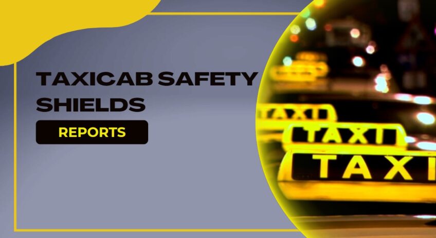
3.1 Angle of Incidence
The angle between the line of flight of the bullet and the perpendicular to the plane tangent to the point of impact (see fig. I). Also known as angle of obliquity.
3.2 Fair Hit
A hit that impacts the ballistic resistant protective material at an angle of incidence no greater than 5 degrees, and is at least 5 cm (2 in) from a prior hit or the edge of the test specimen and at an acceptable velocity as defined in this standard. A bullet that impacts too close to the edge or a prior hit and/or at too high a velocity, but does not penetrate, shall be considered a fair hit for the determination of nonpenetration.
3.3 Full Metal Jacketed (FMJ) Bullet
A bullet made of lead completely covered, except for the base, with copper alloy (approximately 90 copper-10 zinc).
3.4 Jacketed Soft Point (JSP) Bullet
A bullet made of lead completely covered, except for the point, with copper alloy (approximately 90 copper-10 zinc).
3.5 Lead Bullet
A bullet made of lead alloyed with hardening agents.
3.6 Penetration
Perforation of a witness plate by any part of the test specimen or test bullet, as determined by passage of light when held up to a 60-W light bulb.
3.7 Strike Face
The surface of a ballistic resistant protective material designated by the manufacturer as the surface that should be exposed to (face) the weapon threat.
3.8 Semiwadcutter
A bullet shape characterized by a flat nose and a tapered section leading to a cylindrical bullet body with a sharp break where the taper meets the body.
3.9 Witness Plate
A thin sheet of aluminum alloy placed behind a test specimen to determine the potential for an incapacitating injury.
4. REQUIREMENTS
4.1 Acceptance Criteria
A ballistic material satisfies the requirements of this standard if the sample item (see sec. 5.1) meets the requirements of sections 4.2 through 4.4.
4.2 Workmanship
Ballistic resistant protective materials shall be free from dents, blisters, cracks, crazing, chipped or sharp corners, and other evidence of inferior workmanship.
4.3 Labeling
The sample item and each full size panel of ballistic resistance material shall be permanently and legibly labeled and shall include the following information.
- a) Name, designation, or logo of the manufacturer
- b) Type of material, according to section 2 of this standard
- c) Month and year of manufacture
- d) Lot number
- e) Strike face, if any
- f) Certification of compliance with this edition of this standard
Items c and d may be incorporated into a single number, e.g.. a trial number.
4.4 BaIlistic Resistance
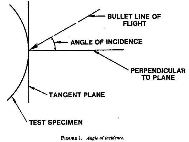
The ballistic resistance of each test specimen of ballistic resistant protective material shall be determined in accordance with section 5.3. The test weapon and ammunition used during this test shall be those specified in table 1 in accordance with the type (threat level rating) specified by the manufacturer (sec. 4.3). Any penetration of the witness plate shall constitute failure.
The ballistic resistance test variables and test requirements are presented in table 1.
5. TEST METHODS
5.1 Sampling
The test specimen shall be a current production sample of the ballistic resistant material at least 30.5 X 30.5 cm ( 12 X 12 in).
5.2 Test Equipment
It should be noted that hand�loaded ammunition may he required to achieve some of the bullet velocities required in the following sections.
5.2.1 Type I Test Weapons and Ammunition
5.2.1.1 22 LR
The test weapon may be a 22 caliber handgun or test barrel. The use of a handgun with a 15 to 16.5 cm (6 to 6.5 in) barrel is suggested. Test bullets shall be 22 Long Rifle High Velocity Lead, with nominal masses of 2.6 g (40 gr) and measured velocities of 320 +/- 12 m (1050 +/- 40 ft) per second.
5.1.1.2 38 Special
The test weapon may be a 38 Special handgun or test barrel. The use of a handgun with a 15 to 16.5 cm (6 to 6.5 in) barrel is suggested. Test bullets shall be 38 Special round-nose lead, with nominal masses of 10. g (158 gr) and measured velocities of 259�15 m (850�50 ft) per second.
5.2.2 Type II-A Test Weapons and Ammunition
5.1.1.1 Lower Velocity 357 Magnum
The test weapon may be a 357 Magnum handgun or test barrel. The use of a handgun with a 10 to 12 cm (4 to 4.75 in) barrel is suggested. Test bullets shall be 357 Magnum jacketed soft point, with nominal masses of 10.2 g (158 gr) and measured velocities of 381�15 m (1250�50 ft) per second.
5.2.1.1 Lower Velocity 9 mm
The test weapon may be a 9 mm handgun or test barrel. The use of a handgun with a 10 to 12 cm (4 to 4.75 in) barrel is suggested. Test bullets shall be 9 mm full metal jacketed, with nominal masses of 8.0 g (124 gr) and measured velocities of 332�12 m (1090�-40 ft) per second.
5.2.3 Type II Test Weapons and Ammunition
5.1.3.1 Higher Velocity 357 Magnum
The test weapon may be a 357 Magnum handgun or test barrel. The use of a handgun with a 15 to 16.5 cm (6 to 6.5 in) barrel is suggested. Test bullets shall be 357 Magnum jacketed soft point, with nominal masses of 10.2 g (158 gr) and measured velocities of 425�15 m (1395�50 ft) per second.
5.2.3.1 Higher Velocity 9 mm
The test weapon may be a 9 mm handgun or test barrel. The use of a handgun with a 10 to 12 cm (4 to 4.75 in) barrel is suggested. Test bullets shall be 9 mm full metal jacketed, with nominal masses of 8.0 g (124 gr) and measured velocities of 358f 12 m (I 175�40 ft) per second.
5.2.4 Type III-A Test Weapons and Ammunition
5.2.4.1 44 Magnum
The test weapon may be a 44 Magnum handgun or test barrel. The use of a handgun with a 14 to 16 cm (5.5 to 6.25 in) barrel is suggested. Test bullets shall be 44 Magnum, lead semiwadcutter with gas checks, nominal masses of 15.55 g (240 gr), and measured velocities of 426�15 m (1400�50 ft) per second.
5.1.4.1 Submachine Gun (SMG) 9 mm
The test weapon may be a 9 mm SMG or test barrel. The use of a test barrel with a 24 to 26 cm (9.5 to 10.25 in) barrel is suggested. Test bullets shall be 9 mm full metal jacketed, with nominal masses of 8.0 g (124 gr) and measured velocities ot426�15 m (1400�50 ft) per second.
5.2.5 Type III Test Weapon and Ammunition
The test weapon may be a rifle or a test barrel chambered for 7.62 mm (308 Winchester) ammunition. The use of a rifle with a barrel length of 56 cm (22 in) is suggested. Test bullets shall be 7.62 mm full metal jacketed (U.S. military designation M80), with nominal masses of 9.7 g (150 gr) and measured velocities of 838�15 m (2750�50 ft) per second.
5.2.6 Type IV Test Weapon and Ammunition
The test weapon may be a rifle or a test barrel chambered for 30-06 ammunition. The use of a rifle with a barrel length of 56 cm (22 in) is suggested. Test bullets shall be 30 caliber normal piercing (U.S. military designation APM2), with nominal masses of 10.8 g (166 gr) and measured velocities of 868�I5 m (2850�50 ft) per second.
5.2.7 Special Type Test Weapon and Ammunition
The test weapon, cartridge type, bullet construction, bullet caliber, bullet mass, and bullet striking velocity must all be specified by the user.
5.2.8 Chronograph
The chronograph shall have a precision of 1 µs and an accuracy of 2 µs. Its triggering devices shall be of either the photoelectric or conductive screen type.
5.2.9 Support Fixture
The test specimen shall be supported by a fixture that permits its position and attitude to be readily adjusted so that it is perpendicular to the line of flight of the bullet at the point of impact.
5.2.10 Witness Plate
The witness plate shall be a 0.5 mm (0.020 in) thick sheet of 2024-T3 or 2024-T4 aluminum alloy and shall be placed and rigidly affixed perpendicular to the line of flight of the bullet and 15 cm (6 in) beyond the armor under test.
,5.3 Ballistic Resistance Test
‘Condition the test specimen at a temperature of 20 to 28 ‘C (68 to 82 ‘F1 for at least 24 h prior to test.
Place the triggering devices 2 and 3 m (6.6 and 9.8 ft), respectively, from the muzzle of the test weapon as shown in fig. 2, and arrange them so that they define the planes perpendicular to the line of flight of the bullet. Measure the distance between them with an accuracy of 1.0 mm (0.04 in). Use the time of flight and distance measurements to calculate the velocity of each test round.
After the specified test weapon bas been supported, leveled, and positioned, fire one or more pretest rounds (as needed) through a witness plate to determine the point of impact.
Place the test specimen in the support fixture and position it 5 m (16 ft) from the muzzle of the test weapon. Then position an unperforated witness plate 15 cm (6 in) beyond the test specimen. Fire a test round and record the velocity of the bullet as measured by the chronograph. Examine the witness plate to determine penetration, and examine the specimen to see if the bullet made a fair hit.
If no penetration occurred, reposition the test specimen and repeat the procedure with additional test rounds until the test is completed. Space the hits as evenly as possible so that every portion of the test specimen is subject to lest.
- Z26.1-1983
- Revision of ANSI Z26-1.1977
- and Z26.1a-1980
American National Standard
- for Safety Glazing Materials
- for Glazing Motor Vehicles
- Operating on Land Highways-
- Safety Code
- Secretariat
- Society of Automotive Engineers, Inc
- Approved August 15,1983
- American National Standards Institute, Inc
Foreword
(This Foreword is not part of American National Standard Z26.1-1983.)
The American Standard Safety Code, Z26.1 �1938, was developed by a sectional committee, national in scope, functioning under the procedure of the American Standards Association and under the joint sponsorship of the National Bureau of Casualty and Surety Underwriters (now the American Insurance Association) and the National Bureau of Standards. lt was the first of several separate codes to be developed within the scope of Standards Committee Z26 on Specifications and Methods of Test for Safety Glazing Materials. That scope is as follows:
Specifications and methods of test for safety glazing material (glazing material designed to promote safety and reduce or minimize the likelihood of personal injury from flying glazing material when the glazing material is broken) as used for windshields, windows. and partitions of land and marine vehicles and aircraft.
Since the original formulation of the American National Safety Code, Z26.1-1938, the development of synthetic plastic materials has so far advanced that a number of them appcar to be practical for certain uses as safety glazing materials for glazing motor vehicles operating on land highways; therefore, in the 1966 edition of this standard, both the foreword and code were modified to the extent necessary to include these synthetic plastic materials along with glass under the general term of “safety glazing materials” reserving the use of the word “glass” as applying only to the ceramic material, and of the word “plastic” as applying only to synthetic, organic, plastic materials.
Early in its deliberations, the Z26 Committee recognized the fact that no one set of specifications or methods of test could well apply to safety glazing materials as used for all purposes. Therefore, the members decided to prepare a separate code for each of the major usages included in the scope of the main project. In keeping with that decision, this code, as its title indicates, pertains only to “Safety Glazing Materials for Glazing Motor Vehicles Operating on Land Highways.”
It is hoped that the test procedures and performance requirements detailed in this standard may be uniformly adopted by motor vehicle commissioners and other interested regulatory officials as the basis for their approval of the safety glazing materials in motor vehicles coming within their jurisdiction, or for incorporation in their regulations; that they may serve as a guide to automobile manufacturers as to the safety glazing materials which will be acceptable to such officials; and that they may enable the consumer (the commercial operator and the general public) to have assurance that the safety glazing materials in the motor vehicle that is purchased should reduce, in comparison with glass of ordinary types, the likelihood of injury to persons riding in such motor vehicles by these safety glazing materials whether they may be broken or unbroken.
It is the fundamental purpose of this standard to prescribe the functional properties of safety glazing materials in such a manner that they can be used in any place in the motor vehicle for which they possess those mechanical, or optical properties, or both, that are requisite and appropriate. For example, safety glazing materials for windshields must pass a specified group of test requirements, all of which currently can be met only by certain laminated safety glass; however, if and when other safety glazing materials are developed that possess properties such that they, too, fulfill the requirements of the prescribed tests for this location, they may also be used; and similar reasoning would apply for other locations. This standard is designed to serve two purposes: (1 ) to afford a basis for standards for adoption in regulations by governmental regulatory bodies; or (2) for use by motor vehicle commissioners or others as reference standards in such cases as they may have discretionary authority to adopt these or other standards in connection with the approval of safety glazing materials or other items of use in or on a motor vehicle.
This standard does not state that safety glazings shall be used or to what extent they shall be used in glazing motor vehicles. Such requirements rest with either the legislative or administrative authority. When by law or regulation escape or emergency egress openings are required and when such requirement is met by use of glazed openings, Test 25 (see 5.25) is provided as a means of measuring and establishing the escape value of the safety glazing material.
This standard, which is the result of extended and careful consideration of available knowledge and experience on the subject, is intended to provide minimum requirements that are recommended for use, adoption, and enforcement by federal, state, and local administrative authorities. It is recommended that this standard should not be incorporated in any statute.
Caution should be exercised not to make laws and regulations dealing with this subject so inflexible as to preclude subsequent adoption of technological advancements in the development of safety glazing materials.
Except for special requirements for specified locations, safety glazing materials of six general types can meet some or all requirements detailed in this standard. All six types are commercially available today. Each of them possesses its own distinctive safety characteristics. The six types may be briefly described as follows:
(1) Laminated Glass. This consists of two or more pieces of sheet, plate, or float glass bonded together by an intervening layer or layers of plastic material. It will crack or break under sufficient impact, but the pieces of glass tend to adhere to the plastic. If a hole is produced, the edges are likely to be less jagged than would be the case with ordi- nary annealed glass.
(2) Tempered Glass. (Other terms such as “heat treated glass,” “heat toughened glass,” “case hardened glass,” and “chemically tempered glass” are used also.) This consists of a single piece of specially treated sheet, plate, or float glass possessing mechanical strength substantially higher than annealed glass. When broken at any point, the entire piece breaks into small pieces that have relatively dull edges as compared to those of broken pieces of ordinary annealed glass.
(3) Wire Glass, This consists of a single piece of glass with a layer of meshed wire completely imbedded in the glass but not necessarily in the center of the glass.
(4) Plastic. A plastic is a material that contains as an essential ingredient one or more organic polymeric substances of large molecular weight, is solid in its finished state, and, at some stage in its manufacture or processing into finished articles, can be shaped by flow.
(5) Multiple Glazed Unit. This consist of two or more sheets of glazing material separated by an airspace or spaces and glazed in a common mounting. For the purposes of this standard, multiple glazed units are divided into two classes:
(a) Class 1 comprises multiple glazed units in which each component single layer or laminated layer complies with the appropriate requirements of this standard.
(b) Class 2 comprises multiple glazed units in which any component single layer or laminated layer does not comply with the appropriate requirements of this standard.
(6) Bullet Resisting Glaring. This consists of one or more layers of glass bonded together with one or more layers of transparent plastic or of transparent plastic material solid or laminated, that can meet the bullet-resisting requirements of this standard.
The Z26 Committee and the Secretariat believe that this standard reflects the best current technology in the art of automotive glazing. It is recognized that new developments are to be expected in safety glazing materials, and that revisions of the standard will be necessary as the art progresses and as further experience is gained. It is felt, however, that uniform requirements are very much needed, that the standard in its present form permits the use of the more desirable types of safety glazing materials now commercially available, and that it distinguishes between the better and the poorer grades of those types, as well as prescribing and, in some cases, limiting the places at which certain types may be used.
The 1983 revision of the standard recognizes a new class of glazing materials, Glass-Plastic Laminated Glazing (Item 1 A). The tests to define the characteristics of such glazing as suitable for windshield use address all of the requirements of conventional laminated glass windshields. Special attention is given to the inner plastic surface to ensure that durability is adequate to meet the requirements of driver visibility. For this, tests for weathering, chemical resistance, and abrasion resistance have been added. Footnotes to this standard are included for purposes of clarification and are not part of American National Standard Z26.1-1983.
Suggestions for improvement of this standard will be welcome. They should be sent to Society of Automotive Engineers, Inc, 3001 West Big Beaver, Troy, MI 48084. This standard was processed and approved for submittal to ANSI by American National Standards Committee on Specifications and Methods of Test for Safety Glazing Material, Z26. Committee approval of the standard does not necessarily imply that all committee members voted for its approval.
R L. Morrison, Chairman
P. Couhig, Secretary